LDR INTERFACING WITH ARM
An LDR or Light Dependent Resistor is also known as photo resistor, photocell, photoconductor. It is a one type of resistor whose resistance varies depending on the amount of light falling on its surface. It demonstrate the principle of LDR interfacing with ARM LPC2148.
Synopsis

An LDR or Light Dependent Resistor is also known as photo resistor, photocell, photoconductor. It is a one type of resistor whose resistance varies depending on the amount of light falling on its surface. It demonstrate the principle of LDR interfacing with ARM LPC2148. When the light falls on the resistor, then the resistance changes. These resistors are often used in many circuits where it is required to sense the presence of light. Resistance will be decrease when the light increases, In day time the output resistance will be less compared than night time.

Description

ARM is one of the major options available for embedded system developer. LPC2148 is the widely used IC from ARM-7 family. It is manufactured by Philips and it is pre-loaded with many inbuilt peripherals making it more efficient and a reliable option for the beginners as well as high end application developer.

ARM is a family of instruction set architectures for computer processors based on a reduced instruction set computing (RISC) architecture developed by British company ARM Holdings .A RISC-based computer design approach means ARM processors require significantly fewer transistors than typical processors in average computers. This approach reduces costs, heat and power use. These are desirable traits for light, portable, battery-powered devices including smartphones, laptops, tablet and notepad computers and other embedded systems. A simpler design facilitates more efficient multi-core CPUs and higher core counts at lower cost, providing higher processing power and improved energy efficiency for servers and supercomputers.


The ARM LPC2148 features are as follows:

1. Architecture: ARM v4T

2. Processor: ARM7-TDMI-S

3. Instructions: 32-bit ARM and 16-bit Thumb

4. Debug support: RT Embedded ICE, Embedded Trace interface

5. Static RAM: 32 KB

6. (On-chip)Additional: 8 KB for USB DMA

7. Flash Program: 512 KB

8. Mem.(On-chip)Programming: ISP/IAP via on-chip boot-loader program

9. GPIO No. of pins: up to 45 (fast GPIO lines, 5V tolerant), Configurable to fast GPIO

10. External Interrupts: Four; No. of pins: Nine

The ARM LPC2148 has two ports Port 0 and Port 1 respectively each port contains 32-bits for I/O operations. The Port 0 has 32-bit of I/O pins for individual directions and Port 1 has 32-bits of I/O pins for bidirectional purpose. It has two timers of each 32-bit. It has capable to storing 128-bit memory for interfacing.

Over the last few years, the ARM architecture has become the most pervasive 32-bitarchitecture in the world, with wide range of ICs available from various IC manufacturers. ARM processors are embedded in products ranging from cell/mobile phones to automotive braking systems. A worldwide community of ARM partners and third-party vendors has developed among semiconductor and product design companies, including hardware engineers, system designers, and software developers.

LDR Sensor is a Analog Sensor. These devices depend on the light, when light falls on the LDR then the resistance decreases, and increases in the dark.When a LDR is kept in the dark place, its resistance is high and, when the LDR is kept in the light its resistance will decrease.

An LDR is a component that has a (variable) resistance that changes with the light intensity that falls upon it. This allows them to be used in light sensing circuits.


Light Dependent Resistor (i.e. LDR for short) is basically used to detect the intensity of light and hence, for example, we can detect if a room is dark or lit. They are also known as photoresistors or photoconductive cells. The resistance of LDR is inversely proportional to the intensity of light. Hence under dark conditions the resistance typically rises to around 500K to 5M. Under ambient light the resistance is generally around 2K to 10K. Under very bright light its resistance falls down to around few ohms, for example around 2 to 20 ohms.


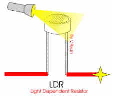
Variation in resistance with changing light intensity


The most common type of LDR has a resistance that falls with an increase in the light intensity falling upon the device (as shown in the image above). The resistance of an LDR may typically have the following resistances:

Daylight= 5000Ω

Dark= 20000000Ω

Applications

• Lighting switch

• Camera shutter control

• Alarm clock

• Street lamps

Proteus design for LDR interfacing with ARM


Orcad design for LDR interfacing with ARM


LDR interfacing with ARM

/*  Name     : main.c
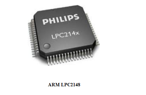
 *  Purpose  : Source code for LDR Interfacing with ARM LPC1248.
 *  Author   : Gemicates
 *  Date     : 2018-09-02
 *  Website  : www.gemicates.org
 *  Revision : None
 */
#include<lpc214x.h>                                                // header file for LPC21XX series
 
#define LCD (0xff<<16)
#define RS (1<<13)                                                 // register select pin
#define RW (1<<14)                                                 // read write pin
#define EN (1<<15)                                                 // enable pin
#define LED (1<<31)
 
void delay_fv(unsigned int x,int y);
 
void lcd_display(unsigned int x);
void cmd(unsigned char m);
void lcd_ini();
void lcd_str(unsigned char *x);
 
void adc_ini();
unsigned long int adc_data();
 
int main()
  {
   unsigned int val;
   PINSEL0=0X00000000;                                             // select PORT0 as GPIO mode 
   IO0DIR=0XFFFFFFFF;                                              // make PORT0 pin as Output mode 
   VPBDIV=0x02;
   adc_ini();
   lcd_ini();
   while(1)                                                        // Repeat(loop) forever
   {
     cmd(0x80);                                                    // clear screen
     lcd_str("LIGHT INT: ");
     val=adc_data();
     lcd_display(val);
      if(val>800) 
        {

           lcd_str("LOW ");
           IO0SET = LED;
        }

      else 
       {
          lcd_str("HIGH");
          IO0CLR = LED;
        }
    }
}
   
void delay_fv(unsigned int x,int y)                                // Time delay function in milli seconds
  {
			 unsigned int i,j;
			 for(i=0;i<x;i++)
			 for(j=0;j<y;j++);
  }
void lcd_display(unsigned int x)                                   // Function to send data to LCD
   {
			 IO0CLR|=(RS|RW|EN|LCD);
			 IO0SET|=(x<<16);
			 IO0SET|=RS;
			 IO0CLR|=RW;
			 IO0SET|=EN;
			 delay_fv(100,200);
			 IO0CLR|=EN;
			 delay_fv(10,10);
   }
  
void cmd(unsigned char m)                                          // Function to send command to LCD
   {
			 IO0CLR|=(RS|RW|EN|LCD);
			 IO0SET|=(m<<16);
			 IO0CLR|=RS;
			 IO0CLR|=RW;
			 IO0SET|=EN;
			 delay_fv(100,10);
			 IO0CLR|=EN;
			 delay_fv(100,10);
   }
 
void lcd_ini()                                                     // Funtion to Initialize LCD
  {
			cmd(0X38);                                 // for using 8-bit 2 row mode and 5x7 Dots of LCD
			cmd(0X0C);                                 // turn display ON for cursor OFF
			cmd(0X06);                                 // display ON
			cmd(0X01);                                 // clear screen
			cmd(0X80);                                 // clear screen
  }
	
	
void lcd_str(unsigned char *x)                                     // Function to display in LCD 
  {
	    while(*x!='\0')
	      {
		        lcd_display(*x);
		        x++;
	      }
  }


void adc_ini()
  {
		AD0CR = 1<<21;	                                   // A/D is Operational
		AD0CR = 0<<21;	                                   // A/D is in Power Down Mode
		PINSEL1 = 0x01000000;                              // P0.28 is Configured as Analog to Digital Converter Pin AD0.1
		AD0CR = 0x00200802;                                // CLKDIV=4,Channel-0.1 Selected,BURST=0,EDGE=0
	
  }
	
unsigned long int adc_data()
   {
	      unsigned long rec;	
              AD0CR |= (1<<24);			                   // Start Conversion
	      while(!(AD0GDR & 0x80000000));
/*Wait untill the DONE bits Sets*/
	      rec = AD0GDR;
	      AD0CR &= ~0x01000000;	                           // Stops the A/D Conversion   				
	      rec = rec >> 6;                                      // data is present after 6 bit
	      rec = rec & 0x3FF;                                   // Clearing all other Bits
	      return (rec);
   }

Error message here!

Show Error message here!


Forgot your password?

Error message here!

Send OTP

Error message here!

Show Error message here!


Lost your password? Please enter your email address. You will receive a password you Need.

Send Error message here!


Back to log-in

Close